 Sliding Mesh Gear Box type" width="" height="" />
In this article, you’ll learn what is gearbox? types of gearbox and how each gearbox works? Explained with diagrams. And also you can download the PDF format file of this article.
What is gearbox or transmission?
The word “transmission” is used for a device that is located between the clutch and the propeller shaft. It may be a gearbox, a torque converter, overdrive, fluid drive, or hydraulic drive.
A gearbox in a car is a mechanical component that transfers power from the engine to the wheels. It is also frequently called a transmission. By switching between gears, the gearbox enables the driver to control the torque and speed of the wheels.
Manual transmission gearboxes have a clutch that engages and disengages the engine from the gearbox, and a gear shift lever that selects different gears. Automatic transmission gearboxes change gears automatically by hydraulic or electronic control.
The type of gearbox a car uses will vary depending on the car’s type, its intended use, and the driver’s preferences.
In a gearbox, the main shaft is the output shaft. This shaft is kept in front of the clutch shaft or engine output shaft, parallel to the lay shaft. This shaft is attached to the gear lever that is used to change the gears.
The output from the engine is sent to the gearbox using a clutch shaft. This shaft allows to engage and disengage the engine output.
Lay shafts are used to transfer power from the engine to the main shaft by continuously meshing the lay shaft gear with the clutch shaft gear.
They are the unique components found in modern synchromesh gearboxes. By keeping the main shaft, lay shaft, and clutch shaft at the same speed, they facilitate smooth gear shifting. They don’t have to move over the shaft for the gears to change.
In essence, gears are just circles with teeth connecting them. A gear transmits a circular motion between two different shafts by rotating and meshing with another gear on the other shaft. Gears come in a variety of shapes and sizes, including spur gear, helical gear, bevel gear, and worm gear.
The driver uses the gear lever to change or shift the gear. The lever moves in a particular way according to design.
 Sliding Mesh Gear Box type" width="" height="" />
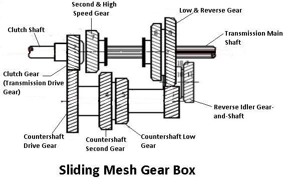
Three other gears like first speed, second speed, and reverse speed gear are also rigidly fixed to the countershaft or also known as layshaft. Two gears mounted on the splined main shaft can be slid by the shifter yoke when the shift lever is operated.
The gears are connected to the corresponding gears of the countershaft. A reverse idler gear is fixed on another shaft and remains connected to the reverse gear of the countershaft.
How sliding mesh gearbox works?
In this position of the gear, the engine power is not transmitted to the rear axle. When the gear is in neutral, the clutch gear transmits the power to the gear on the countershaft, and the countershaft further does not transmit line power to the main shaft. Therefore the output of the gearbox is disconnected from the input of the gearbox.
Remember that in a neutral position, just the clutch shaft gear is engaged to the countershaft gear. Other gears are free, so the transmission main shaft is not rotating.
First or low-speed gear, by operating the gear shift lever, the larger gear on the main shaft is moved along the shaft to mesh with the first gear of the countershaft.
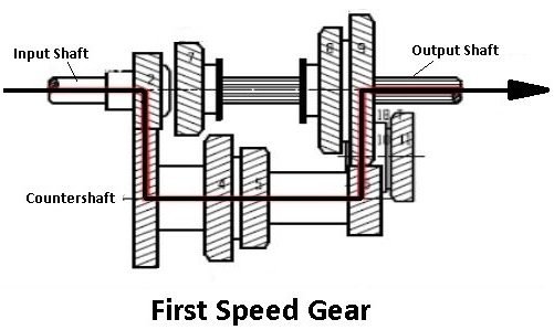
In this, the main shaft and the clutch shaft rotate in the same direction. Since the smaller countershaft gear is engaged with, the larger main shaft gear, a gear reduction of approximately 3:1 is obtained.
That is, the clutch shaft turns three times for each revolution of the main shaft. Besides, gear reduction in the differential at the rear wheels creates a higher gear ratio, about 12:1, between the wheels and the engine crankshaft.
Second speed gear: By operating the gear shift lever, the larger gear of the main shaft is disengaged from the first gear of the countershaft, and then the smaller gear of the main shaft meshes with the second gear of the countershaft.
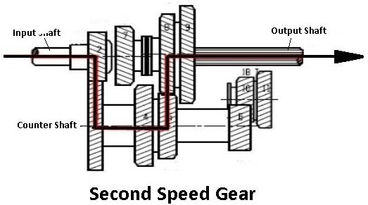
In the second speed gear, the main shaft and the clutch shaft rotate in the same direction. A gear reduction of approximately 2:1 is obtained. The differential gear reduction increases this gear ratio to about 8:1.
Third top or high-speed gear. By operating the crankshaft lever, the second gears of the main shaft and countershaft are disengaged, and then the second and top gear of the main shaft is forced axially against the clutch shaft gear.
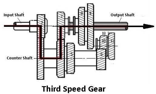
The external teeth of the clutch shaft gear mesh with the internal teeth in the second gear and top gear. The main shaft turns with the clutch shaft, and a gear ratio of 1:1 is obtained. The differential reduction produces a gear ratio of about 4:1 between the engine crankshaft and the wheels.
Reverse gear, by operating the crankshaft lever, the larger gear of the main shaft meshes with the reverse idler gear. The reverse idler gear is always in mesh with the countershaft reverse gear.
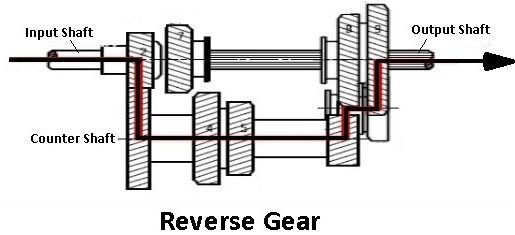
Interposing the idler gear between the countershaft reverse gear and the main shaft bigger gear, the main shaft turns in the direction opposite to that of the clutch shaft. This changes the rotation of the wheels from forward to backward so that the vehicle backs.
In this type of gearbox, all the gears of the main shaft are in constant mesh with the corresponding gears of the countershaft (layshaft). As the figure shows, two sliding dog clutches are provided on the main shaft.
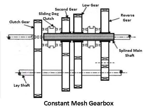
The one sliding dog clutch is placed in between the clutch gear and the second gear, and the other is placed in between the first gear and reverse gear. All gears are free on the splined main shaft.
The dog clutch slides on the main shaft to rotate with it. All the gears on the countershaft are fixed with it. When the left-hand dog clutch is made to slide to the left through the gearshift lever, it meshes with the clutch gear, and the top speed gear is achieved.
When the left-hand log clutch meshes with the second gear, the second speed gear is obtained. Likewise, by sliding the right-hand dog clutch to the left and right, the first gear and reverse gear are obtained.
In these types of gearbox, all the gears are in constant mesh. They are safe from damage, and an unpleasant grinding sound does not occur while engaging and disengaging them.
Modern cars use helical gears and synchromesh devices in the gearboxes, that synchronize the rotation of gears that are about to mesh. This eliminates clashing of the gears and makes gear shifting easier.
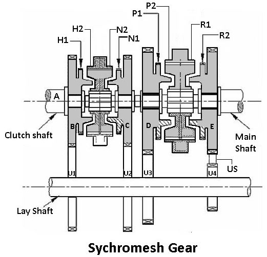
This type of gearbox is similar to the constant mesh gearbox. The synchromesh gearbox is provided with a synchromesh device by which the two gears to be engaged are first taken into frictional contact, which adjusts their speed, after which they are engaged easily.
In most vehicles, the synchromesh devices are not fitted to all the gears. They are fitted only on the top gears. Reverse gear, and sometimes the first gear, do not have synchromesh devices. Because they are intended to be engaged when the vehicle is stationary.
When the gear lever is moved, the synchromesh cone meets with a similar cone on the pinion. Due to friction, the rotating pinion is, made to rotate at the same speed as the synchromesh unit. To give a positive drive, further movement of the gear lever enables the coupling to override several springs loaded balls and the coupling engages with the dogs on the ride of the pinion.
Since both pinion and synchromesh units are moving at the same speed, this engagement is necessary before engaging the dog teeth so that the cones have a chance to bring the synchronizer and pinion to the same speed.
In many aspects, the automatic transmission is better. They are typically found in modern automobiles. Typically, they cost a lot. By simply pressing the accelerator, infinite gear ratios can be achieved.
This allows the driver to choose between forward or reverse, park, neutral drive, and sport driving modes. The gear chosen by the drive will automatically determine the gear ratios and the timing of the meshing. Since an automatic gearbox does not require a clutch pedal, it only has two pedals.
In ordinary gearing, the axes of the various gears are fixed, the motion of the gears being simply rotations about their axes. In epicyclic gearing, at least one gear not only rotates, about its own axis but also rotates bodily about some other axis.
These types of gearbox are the most widely used automatic transmission system. In an automatic transmission system, there is only an accelerator and brake are provided. So there will not be any clutch pedal or gear lever available on the vehicle.
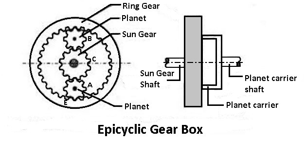
It has an epicyclic gear arrangement. As the figure shows the front view and side view of the gearbox. This gearbox type, has three gears sun gear, planet gear, and ring gear. The sun gear is mounted on the sun gear shaft. The planet gear is mounted on the planet carrier and the ring gear is mounted on the planet carrier shaft.
The ring gear has internal gears that are meshes with planet gear to rotate with it. An epicyclic gearbox is an arrangement of locking gear. If one gear is locked remaining two gear will be act as input and output. For example, if the sun gear is locked the ring gear and planet gear act as input and output members.
This typical arrangement will be available of locking the gear at the same time and taking the output power from anyone gear and giving the power input to any gear so such kind of arrangement will be available.
So by locking anyone’s gear, we can get a very different speed. The specialty of this particular epicyclic gearbox is we can achieve a wider variety of variations in speed.
An automatic transmission uses a hydraulic torque converter as a type of fluid coupling to transfer power and torque from the engine to the load. To transfer power between the input and output shafts, it combines hydraulic pressure and fluid flow.
Hydraulic torque converter gearboxes include a turbine, an impeller, a highly compressed fluid, and a stator. For determining the various speeds or gear ratios, the stator is used. The accelerator pedal is used to control this.
To direct fluid flow, the stator is positioned between the impeller and the turbine of the torque converter connected to the engine shaft. The turbine is connected to the output shaft, and the impeller is connected to the engine shaft.
These types of gearboxes are especially helpful in automatic transmissions because they let the engine idle while the car is stopped without stalling the engine.
Thank you for reading.
That’s it. We have discussed all the four different types of gearbox but if you still have any questions on this article you can ask in the comment I’ll respond to you. If you like this article then please share it with your friends.
And also you can download the free PDF file of this article by clicking below.
 types of gearbox" width="" height="" />
Subscribe to our newsletter to get notification of our new engineering articles.
Saif M. is a Mechanical Engineer by profession. He completed his engineering studies in 2014 and is currently working in a large firm as Mechanical Engineer. He is also an author and editor at www.theengineerspost.com
Wow, thank you for breaking down the concept of gearbox so clearly! I was really struggling to understand the different types and parts, but these images and explanations made it all click into place. bookmarking this post for future reference
I’m glad you liked my article. Keep visiting.
Mzie FurusaCan I have a copy also about Gearboxes plz on my email [email protected]
The PDF file has been sent to your inbox.